Conductor Clashing on Overhead Lines: Why Wind Trips Feeders and What Covered Conductor Changes
Two phase conductors that touch for a fraction of a second can trip a feeder, and on a bare 11 kV or 33 kV line it takes very little to bring them together. A gust, a sag mismatch or the force of a nearby fault is enough. The breaker opens, the recloser closes, and if the contact repeats the consumers downstream lose supply while a crew patrols the route looking for a fault that left no mark.
That last point is what makes clashing costly. A tree fault leaves a burnt branch. A bird fault leaves a carcass. Clashing leaves nothing, so the same span trips again on the next windy afternoon and the log records it as unexplained.
Why bare conductors clash
Three mechanisms account for most clashing, and a line can suffer from all of them at once.
Wind. Gusts do not load all three phases equally. Each conductor swings on its own natural period, and where phases are close together the swings can bring them into contact in the middle of the span.
Sag mismatch. Phases strung at slightly different tensions, spans of unequal length, old joints and conductors that have crept at different rates all produce phases with different sags. Unequal sags swing out of step, which is the condition that clashes.
Fault forces. Short-circuit current produces strong electromagnetic forces between conductors. A fault elsewhere on the feeder can throw healthy spans together, and when the breaker recloses into a line that is still swinging, the second contact turns a transient fault into a lockout.
How to tell clashing from other faults
Clashing has a recognisable signature, and the data to read it usually exists already. The trip is phase-to-phase rather than phase-to-earth. It clears on reclosure. It clusters on windy days and the patrol finds no debris, no animal and no fallen branch. Where a fault locator or relay record gives a distance, the repeat trips point to the same span or the same few spans.
On a bare line, a close patrol can sometimes confirm it. Look for arc marks, small burnt or pitted strands near mid-span, or bright patches on two adjacent phases. Absence of marks does not rule clashing out, because a contact of a few cycles may leave very little. The pattern in the log is the stronger evidence, and a line that trips in wind with no found cause deserves a span-by-span look at sag and spacing before anyone orders material.
What the usual remedies cost
There are four conventional answers, and each has a price that goes beyond the material.
- Wider phase spacing. Longer cross-arms or taller structures need stronger poles and more right of way, which is exactly what a congested route does not have.
- Interphase spacers. They hold bare phases apart but add hardware to inspect and maintain along the span.
- Tighter stringing and re-sagging. This works until the conductors age or are repaired, then the mismatch returns.
- Underground cable. It removes clashing entirely and removes much of the rest of the fault population too. It is also the most expensive option, and often impractical in rocky or waterlogged ground.
What a covering changes
A covered conductor puts insulation on the phase itself. The stranded conductor carries a semi-conducting screen, an inner layer of carbon-free XLPE and an outer layer of UV-protected, anti-tracking XLPE or HDPE, bonded together. When two covered phases touch in the wind, there is no bare metal contact and the contact does not complete a fault path. APAR describes the product as designed to remove clashing faults in winds and storms.
The covering also changes the spacing question. Because brief phase contact is no longer a fault, a utility can reduce the phase-to-phase distance on new structures, and APAR notes lower tower costs as a result. How far spacing can be reduced is a design decision for the utility under its own standards. The covering is not a licence to ignore clearances, and a covered conductor must still be treated as live.
Fitting it to an existing line
For most reconductoring jobs, the practical advantage is that covered conductor is designed to be installed on an existing bare-conductor network without changing poles, cross-arms or insulators in the same span. It is self-supporting on pole spans of 60 to 70 metres with no messenger wire. The range covers 11 kV to 132 kV in six voltage classes, in conductor sizes from 100 to 400 mm², with AAAC, ACSR, ACSS and AL59 ACS cores.
Two checks apply before ordering. The covering adds weight compared with a bare conductor of the same size, so pole strength and sag must be checked against the covered conductor’s own table. And covered lines need the right accessories and arc protection, because a covered line behaves differently in a lightning or power-arc event from a bare one. Both are covered in the MVCC accessories and installation guide.
APAR recommendation
Start with the evidence the network already holds. Pull the recloser and breaker logs for the past two years, pick out the trips that cleared on reclosure, and match them against weather records. Spans that trip repeatedly on windy days with no cause found are the clashing candidates. Record their span lengths, pole types and phase arrangement using the covered conductor site survey checklist, and choose the conductor core with the core options guide.
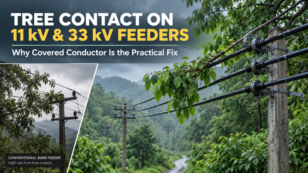
Where the same feeder also runs through trees, the case for covering is stronger, because one conductor change addresses both fault types. That argument is set out in Tree Contact on 11 kV and 33 kV Feeders, and the voltage classes and sizes are laid out in the covered conductor selection guide.
The full range, accessories and approvals are on the APAR covered conductor page, and the wider cable portfolio is on the electrical cables page. Technical particulars and test certificates are available from APAR on request.
Related
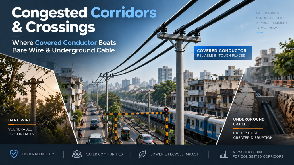
Congested Corridors and Crossings: Where Covered Conductor Beats Bare Wire and Underground Cable
Heat and Vibration in Engine-Bay Wiring: Why Harnesses Fail and How to Specify Against It